Designing an IOT Solar Charge Board - Version 1 - 19-09-2022
Project Goals
This is a hobby project to create a solar MPPT charger for my low power IOT projects. This post will document the design and testing of this chip. I'm not an electrical engineer, so errors are expected. Here are my requirements for the MPPT charging board:
-
Small form factor
The circuit board should fit into small enclosures. A smaller PCB for the MPPT charging board leaves more space for the microcontroller circuit board. Although not every IOT project has size constraints, for those that do, smaller is better. -
Use an energy storage method that can last many years
The power storage method should last more than 10,000 battery cycles. Replacing batteries is one of my pet peeves; no one likes replacing batteries. People who do are weird. -
3.3V output voltage for power powering a microcontroller
Microcontrollers generally don't work well with fluctuating voltage. STM32 and ESP32 chips can't handle voltages above 3.6V without additional circuitry. Commonly used lithium-ion batteries have a voltage range between 3.0V and 4.2V. Recent developments like the Raspberry Pi Pico (W) are more forgiving in this aspect. However, I don't want to limit myself to one family of microcontrollers for my projects.
Component selection
MPPT IC
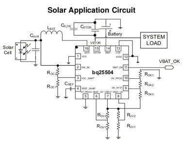
There are various MPPT charging ICs available. LT3652 is a commonly used one. However I chose for the BQ25504. Why this chip? First, it's made by Texas Instruments, a well-known company with good products. Secondly, the specifications on the datasheet are reliable. Finally, the well-written documentation makes the design process easier.
Some of the features of the features of the BQ25504 that we're interested in are the overvoltage and undervoltage protection. These features are essential for battery-operated devices. Battery undervoltage causes an irreversible chemical reaction inside the battery, which severely limits the battery's lifespan. Battery overvoltage protection is even more important, as overvoltage may cause a fire or even an explosion of the battery.
3.3V Output
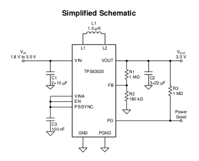
Most modern microcontrollers operate with a voltage of 3.3V. One of the most commonly used ICs for 3.3V in IoT projects is the AMS1117 low-dropout regulator (LDO). It can convert a 5V USB voltage to 3.3V. However, since our battery does not provide a stable 5V, we will need to find another solution to obtain the desired 3.3V. A buck-boost converter is a good choice in this case, as the battery voltage can be both above and below 3.3V depending on the charge level. For this design, I have chosen a Texas Instruments chip, specifically the TPS63020, due to its ultra-low quiescent current of 25 μA. A low quiescent current is especially important during the winter months when the small solar cell may not produce much energy.
Battery
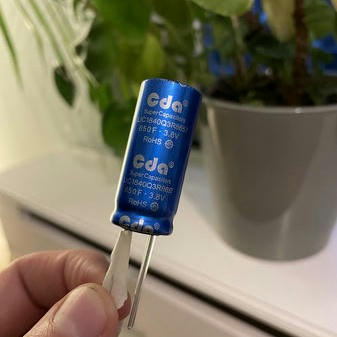
I've opted for an lithium-ion capacitor (LIC) in this project instead of a more traditional li-ion or liPo battery. So why the LIC in this project? A typical rechargible battery has a lifespan of 2-3 years or about 500 charge cycles. A LIC has a significantly longer lifespan, the one I chose is rated up to 50,000 cycles. Regular supercapacitors would have worked as well, but these have a relatively high self-discharge rate. If this self-discharge rate exceeds the energy harvested by our solar panel we would have been out of luck. The LICs I've bought are 650F and rated 2.5V to 3.8V. I've ordered 5 from Aliexpress for ~€40. Search for 'LIC 3.8V CDA' if you want he exact same ones I've got. The total capacity is roughly 235mA, more than enough for low-power applications to survive during the night.
Solar
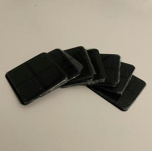
The solar cells we are using are inexpensive 2V Aliexpress solar cells branded 'Sunyima' and measuring 50mm x 50mm. However, the 2V rating is just an estimate, and individual cells can vary by up to 0.3V in Voc (open-circuit voltage) under direct sunlight, according to my testing. Any solar cell with a voltage below 3V should work with the BQ25504. Just be sure to choose a solar cell with dimensions that are suitable for your project.
The BQ25504 has a cold-start voltage of 600mV, after which it will start harvesting solar energy. It will continue to do so until the voltage drops below 130mV. Its quiescent current of <330 nA is ideal for low-power IoT projects.
PCB Design
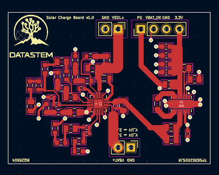
The resistors around the BQ25504 set the battery overvoltage (VBAT_OV) to 3.8V and undervoltage (VBAT_UV) to 2.5V, matching the lithium-ion capacitor specifications. But does it actually work? The charging circuit seems to work, as the lithium-ion capacitor was charged from 3.2V to 3.76V in roughly 14 days with about 2.5 hours of direct sunlight per day. However, the 3.3V output does not seem to be functioning correctly. Can you spot the mistake on the PCB? I made the mistake of placing the VIN capacitors of the TPS63020 in parallel with the power coming from the BQ25504, rather than between VIN and ground, as specified in the datasheet. Another mistake I made was tying the enable pin (EN) to ground, which prevents the TPS63020 from functioning at all!
I will publish the KiCad schematic and drawings for this board at a later date, probably with version 2. If you are interested in them, please send me an email at thomas at datastem .nl.
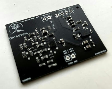
Assembly
I have chosen to use JLCPCB to assemble my PCB. They are a low-cost Chinese manufacturer with excellent build quality. To reduce assembly costs, I have used mostly 'basic parts' for the resistors and capacitors. It cost me €64 to fabricate 5 boards and ship them to Western Europe. The required bill of materials and placement files will be published along with the updated KiCad schematics when version 2 is ready.
Assembled Chip
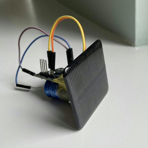
So here it is: My solar MPPT charger for small IOT projects. I have achieved 2 out of 3 of my project goals:
- The PCB is currently 40 x 30 mm, which is small enough for most projects. In version 2, I plan to make it even smaller! When fully assembled, the project including the solar cell and lithium-ion capacitor measures approximately 50 x 50 x 50 mm.
- The lithium-ion capacitor is expected to last for many years before needing replacement, but only time will tell.
- Unfortunately, due to two mistakes in the TPS63020 schematic, I was unable to create a working 3.3V output. In version 2, I will fix this issue.
Thank you for reading this article and I hope you found it informative and useful. All of the components are listed below.